Feature - New Group: Helix #389
Comments
|
This is excactly how I made it for NoteCAD. |

|
I started working on this last night and have some questions about internals. Getting the surface patches (control points) correct was easy but the trim curves are tricky. I've copied SShell::MakeFromRevolutionOf() as a starting point for SShell::MakeFromHelicalRevolutionOf(). The part where trim curves are created is very confusing due to me not understanding all the requirements of the internal data structures. Is there any explanation of what Remap is doing? Would it be OK to trim a surface patch using curves constructed from the same control points that define the surface? That would seem to be an easy function to implement for surface patches that don't have holes. Is there some kind of linkage needed between patches that are part of the same surface? Are the curves reused just to save memory or is it important that shared edges not be replicated? From a code point of view I also copied SSurface::FromRevolutionOf() to SSurface::FromHelicalRevolutionOf and include two additional distance parameters to specify how far along the axis the start and end of the revolved surface are. Should this stay a separate function or should older code use the new version and pass zeros for these new parameters? It should produce the exact same results in that case with less new code. |
|
Only @jwesthues can answer this questions. |
|
These
A single function for both helical and circular sweeps seems reasonable to me, as long as it generates the exact same output as now when the pitch is zero. I'd suggest using some function of the chord tolerance to choose how finely to approximate the helical surface, rather than adding another user setting. |
|
Here's a pic so far. I'm creating a helix with hard coded angle, pitch, and number of segments (5). These will become parameters after there is a way to for the user to determine them. For now I've patched regular rotation to call this until I work my way up toward the UI and add a new method to create a group. That's why the circles are there - they are part of a regular revolve group. One thing I have seen is that when you select a segment and point to revolve around, sometimes the direction of the axis is reversed so it spirals the other way. Or maybe the sketch normal is flipping, I think I've seen that in other experiments. There is a long way to go on this but the code is starting to make more sense. @jwesthues I noticed that in the regular revolution tool, the circular trim curves are created directly from the control points of a surface, which are created by rotating a point around an axis. The ones that are copies of the sketch curve are rotated via quaternion. I'm wondering if very slight numerical differences between these are relevant. What do you think? |

|
Cool, looks helical. There's no need for the NURBS trim curves and Of course, the Booleans often break when given coincident curved surfaces. That difference is the least of your problems there, though. "Close but not exactly equal" problems in SolveSpace usually involve differences on the order of |
|
@phkahler Very nice progress! I'm looking forward to having this feature. |
|
Some comments and questions on doing this. It will probably have to be split into two kinds of group creation - rotate/revolve and helix. Revolve seems more useful and often will involve rotation around a line in the sketch. When that happens the line/axis does not sweep out a surface, so it is fundamentally different from most hilixes. The NURBS handling in solvespace doesn't seem to like highly twisted surfaces and does like a helical extrusion along a line in the sketch. So these operations seem like they will be easier if handled separately. I can not figure out how to copy sketch entities to the "new" end of the helix. Getting the surface control points and trim curves there was reasonably easy. But I'm looking at Group::Generate() -> case:Type::EXTRUDE and case:Type::LATHE and it's just confusing. What does CopyEntity() actually do? What are the remap types for? Where are the expressions for extruded end points actually created? I expected a new point to be an existing point plus the sketch normal scaled by a free parameter, but that does not seem to exist in the code. @jwesthues this code appears fairly readable, but something is missing and for as clear as some parts are, others are just confusing me. Also, there is a severe problem with normal vectors. Maybe I'm off base, but I think extruding a sketch should produce the same geometric result regardless of which way you're looking at it. Go ahead, draw a rectangle, extrude it and rotate a little to the side to see that it came "out of the screen". Undo the extrusion, rotate 180 degrees so you're viewing the "back" of the sketch and do a new extrusion. It will come out of the screen at you rather than going where it did the first time. While this may seem intuitive to a CAD user, it does not make sense to me as a programmer, nor can I see where it happens in the code. I fear this is also related to some other problems with normal vectors.... If I do a simple revolve through an angle (non-helical) I get what you'd expect - a partial ring with two end caps. If I drag the points in the original sketch such that the left and right sides (I revolved a rectangle in the upper right quadrant) switch places, the extrusion flips from "into" to "out of" the screen. I gets worse. If I comment out the code: which I borrowed from SShell::MakeFromRevolutionOf(), then sometimes moving the sketch points around will turn the surface red - which I believe means the surface normals are facing inward rather than outward. So that code is fixing a problem in the lathe function, but it's not fixing it all. You don't see the angle reversal in a lathe because it goes a full 360 degrees so it looks the same either way. This normal problem happens if I use a sketch line for the axis and select the origin as the point to revolve around. It all goes away if I use one of the basis vectors at the origin as the axis and the origin as the point. I can understand that if my axis is a segment connecting two points, swapping those points may reverse the direction of rotation, but there is more going on and more cases than can be explained by that alone (I think). There is a similar flip in the straight extrusion code. A while back I created a frustum (surfaces only, couldn't figure out the entities) by scaling one set of end points. As I dragged the sketch around it would flip which end was smaller and larger. Very disturbing and I couldn't identify when it would flip. Again I commented out the code to flip the normal. That problem IIRC went away and instead of swapping big and small ends, the surface would turn red. At the moment I just want to figure out how to make entities on the new end of my revolve. What and where should the code go for this? |
|
See above for some notes on When we create a new extrusion group, we default the extrusion vector to the GUI viewport normal Lines 420 to 422 in a7b2f28 Tracking normals is always a pain. As you observe, it takes considerable effort to keep that consistent. Since the direction of rotation didn't matter for any existing group types, I wouldn't have bothered. I have no special advice there, beyond carefully thinking through all the geometry, and debugging graphically (render arrows pointing out of all your edges etc., and confirm they point as expected) when in doubt. |
|
About axis and Direction - I can suggest you look here |
|
@whitequark Off topic - I grabbed a fresh copy of master and it won't build per the instructions. There are complaints about Q3DO and flatbuffers. Is there a new dependency/step that isn't covered in the Linux build instructions? Reverting to the commit before that works for me. |
should fix that. It's the same instructions as before, you just need to run them again. |
|
Oh wait, you're right--the Linux instructions aren't quite what I described above. One moment. |
|
See 945a282. |
|
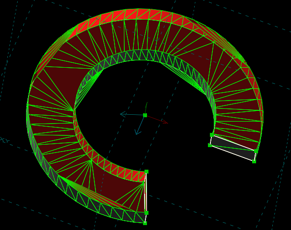
I've pushed some early test code to my geometry branch if y'all want to have a look. It adds Revolve to the menu and creates a fixed rotation angle solid from a sketch. Don't try to revolve around a sketch line yet, it will crash (use a line and separate point). I will probably write a revolve-specific function for creating the shell because that case is important (but difficult or invalid with a general helix). For now I'm trying to copy entities using stuff from Rotate which should make the end draggable. This belongs in Group::Generate() under Revolve but I haven't worked it out yet. One interesting bug that has me really confused. The number of sections to rotate is hard coded at 5 in SShell::MakeFromHelicalRevolutionOf. I made a change to allow up to 100. If you change it to higher values than 5, the last section will not work and a bunch of red lines will appear for that last section. No idea why. But for the simpler Revolve function we will not be going beyond 3 sections anyway. Code reviews welcome on what I've got so far. |
|
Small aside: you don't always want to use the minimum number of sections for the angle. A single piece can represent any angle <180 degrees, but as the angle gets bigger the convex hull or axis-aligned bounding box fit looser, slowing coarse intersection tests like those used in the Booleans. That's why I did 90 degrees before. That also has the advantage that subsequent Boolean operations often slice through axis-aligned planes, and therefore don't need to split the surfaces. |
|
My solvespace/geometry branch now has basic REVOLVE support. Still need to fix some things and make the surfaces selectable. But.... @jwesthues I believe there is a bug somewhere in the NURBS code that does not involve booleans. You may check out my branch to reproduce this: I'm using 3 sections here, but it happens with 4 and 5 as well. The number of chords that cut across the center hole always matches the number of sections and are evenly spaced. If I'm not mistaken it is half the arc of the section when it happens - perhaps a bug when the patch is bisected? At other angles many surfaces turn red - even with 4 sections totalling less than 360 degrees, but usually over 300 degrees. In this revolved surface there are no boolean operations and no trimmed surfaces other than the usual outline trim curves, so this looks to be a bug in plain NURBS. I believe I saw it on one of my models once in 2.3 but it manifested as a white line across the bottom of a round hole that did not go all the way through, so I thought it was just an extra line and ignored it. I feel like having these NURBS issues show up without booleans is a good case to explore, but I have not even looked in to that part of the code yet. I have to fix some things with this feature still ;-) |

|
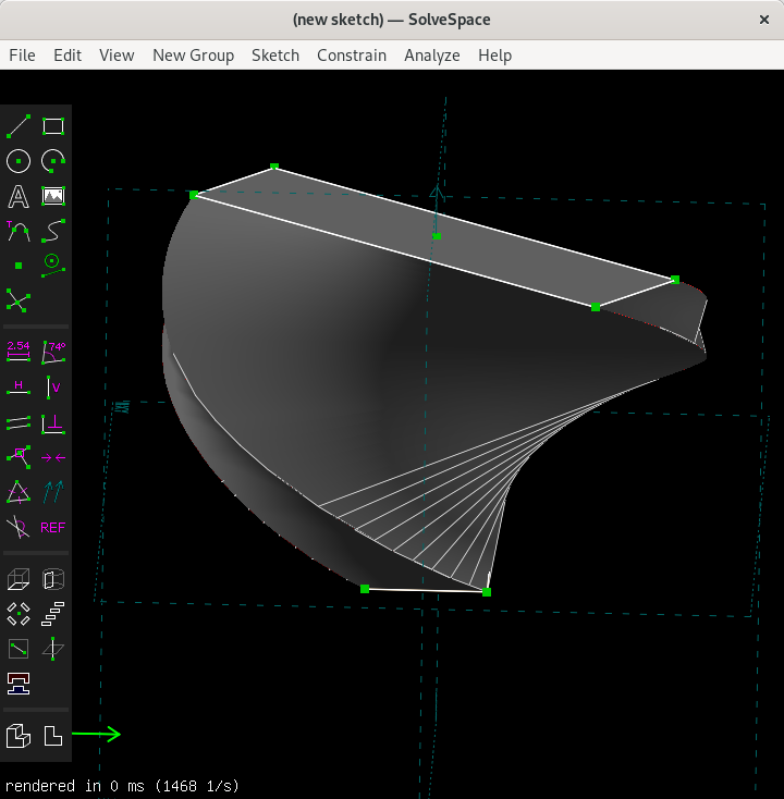
Triangle mesh from one of these. It's similar to above but the top surface is doing something very similar to the bottom. Again, this is not a boolean issue. Still trying to understand a lot of things here... |
|
@jwesthues In the quest to get more consistent behaviour of normal vectors and do fewer checks when making shells, I have an idea. The issues all stem from the function "FindOuterFacesFrom" which determines the loop normal and then sets loop direction CC vs CCW to establish loop normals. This function can flip the loop normal depending on the relative placement of points in the sketch. I propose to pass this function a preferred normal direction, and if one it pick arbitrarily does not match we can swap the u,v vectors (which are arbitrarily picked from points) so the normal matches the one passed in. We can pass in (0,0,0) to leave the behaviour unchanged when called from the places I know nothing about. A quick test suggests this will work. How do I get the sketch/workplane normal vector from in "Group::AssembleLoops" which is where it will be called from? Or is this a bad idea for some reason I don't see yet? |
|
I don't think that solves the right problem. The plane-sketch-to-shell operations need to work correctly regardless of the normal of the plane sketch. The normals of the shell faces should be determined only by the extrusion direction, rotation axis, etc. If the incoming plane sketch normal matters, then that's the bug. |
|
@jwesthues You are probably correct. Now I turn the revolve inside out similar to how it's done in plain extrusions. It was more complex to implement but solves the problem by making both ends of a helix variable - a capability I don't anticipate using otherwise. BTW the problem in the above images seems to be triggered when the number of points along the inner and outer curves differ in certain ways. It's like a tessellation problem but only with NURBS and not when you force to triangle mesh. Sometimes I think it's an off-by-one issue. |
|
Today the Revolve feature in my branch is mostly working. The end can be dragged and constrained. The above pictured rendering errors are gone. You can build on both end surfaces without additional errors that were happening with booleans and coincident surfaces. Some problems and questions remain:
Getting back to actual helical extrusions:
From a UI point of view:
Thoughts or suggestions on these things are more than welcome. |
I'm a bit confused, how are you debugging the code that you don't know where it crashes? In any case I can take a look at that.
That's fine, really. We can always add it later.
I feel like we ought to do better here than just hardcoding values in the text window. Sure, for screws it would be sufficient, what about other use cases? Can you explain the problems that arise when integrating this with the solver?
2-sided revolves can be convenient when carving out a thread inside some other model. You put the origin inside the shell and then revolve it both sides slightly past the surface. This is similar to 2-sided extrusions.
If no one else does it I will draw these icons. Do you mean you need both revolve and helix? |
|
Two sided revolve is in, as well as difference.
It's probably time for me to learn how to use GDB eh? ;-) Got any IDE recommendations on Linux (Fedora)? To make revolves work, I borrowed a lot from other group types. The entities are manipulated the same way as Rotate, curved surface creation is a modified version of Lathe, and the end cap creation code was adapted from Extrude. Rarely did it crash during all this.
Probably. I set out to do Helix, but Revolve was simpler and the UI is nice for just that. There is also the problem of revolving around a line in the sketch, which we can probably fix but will be impossible with helix because the surfaces do some really odd things in that case. IMHO usability issues will warrant separate tools. It's really easy to Revolve something and then constrain the angle between lines on opposite ends. That will be more awkward if the ends can also move up and down. Opinions welcome of course. Try setting the angle between skew lines. Also, apart from the crash and an Icon I think revolve could be considered done. Please test!
I didn't do anything at all inside the solver yet. If we want SS style Helix I'll dig in to the solver and get it to handle entities with additional freedom and then we can decide if this new version of Revolve should be renamed Helix, or if having both variations would be better from the users point of view. |
|
The only commands for GDB that you need to know to debug crashes are "r" (run) and "bt" (backtrace), though make sure you compiled with debug symbols enabled (-g). As for IDE's I can recommend kdevelop, though I'm not sure how well GDB integration will work for you. Another thing you can try is to run solvespace in valgrind to see if there are memory allocation and initialization related bugs that might be causing the crash. |
I use QT Creator. It works good with CMake projects.
Actually this is not looks like hardcoding (for me) and can support any of usecases so I have implemented this as option for NoteCAD (sorry for mentioning this again). If we switch on "angle fixed" we just fixing angle (not add parameter to solver) and it works as constraint. If we uncheck this, we let solver to use our angle parameter as free, so we can drag it (try it yourself). |

NoteCAD is a great project and I am always interested in seeing how others solved some kind of problem in a CAD, so this is useful. "Step/Angle Fixed" looks like a possible solution to me. |
|
@jwesthues Does SolveSpace have a problem with degenerate surfaces? I've been having a crash when Revolving around a sketch line. This would normally create a degenerate surface from the revolved line, but in the code I borrowed from the lathe function it does this: So just for grins I tried leaving those surfaces and trim curves in for revolves and it seems to work fine. I'm wondering if this sounds like a valid solution to the crash or if I should find the problem with leaving those surfaces out. It seems like with the NURBS issues this could be a bad thing, but I even tried doing a difference through that edge with no problem. Do you think this is a valid thing to do, or should I keep trying to find "the problem". |
|
@jwesthues I've got a problem creating arcs for the new Revolve group. They seem to work correctly on a new revolve but if you drag the end so the angle becomes negative the arcs go the wrong way around. For example, drag it so it comes out of the screen instead of going in. The direction of the arcs can be reversed by swapping the constants REMAP_LATHE_START and REMAP_LATHE_END in the Revolve section of Group::Generate but that does not help (it always swaps them). The sign of the angle is not known at the time Generate is called so this is not the right place to fix it. Do you have any suggestions how to resolve this? This is current state of my geometry branch, and has been rebased to master today. @whitequark this is in really good shape with the last couple commits except for this arc bug. |
|
@phkahler OK, now that Revolve is merged, let's discuss the next steps. My understanding is there are generally two things to do:
I can't do (1) personally, but I can look into (2) if you want. Chirality is something I think is a requirement for #77 to work out long term, so it's definitely an important goal. |
|
@whitequark I'm looking into the remapping and solver stuff. The code to create a helical SShell is all there, it's creating the entities with the correct relationships and degrees of freedom that's still new to me. I have a simpler experiment to try first to get a feel for how that's all put together. |
|
@jwesthues Regarding your comment above - on April 10 and continuing to use extrude as an example.. I get that the normal is turned into 3 parameters as shown in your comment. I know where those parameters for groups get created. For extrude those 3 parameters are combined into an expression vector, which is used to create 2 constrain equations that keep that vector orthogonal to the sketch plane. I know where all that happens. I can not find where that vector (or those parameters treated as a vector) is added to the points of an entity to calculate the points of a copy of that entity. Can you tell me exactly where that addition takes place in the code? I need to know in order to create new relations between entities and their copies. |
|
Thanks, I had missed that. But that is doing a numeric computation. I was expecting there to be an expression vector computation of the location of the copied point. Otherwise when you drag a point, how are the constraints enforced? |
|
Lines 534 to 539 in 5df53fc
|
|
Thanks @jwesthues. Also want to bring in @whitequark again. I've been experimenting on a new branch "frustum" which hijacks the Extrude command to produce a frustum group. This produces an extrusion where the new end is a scaled version of the sketch end, and can be moved in any direction (skew is possible). This is my experiment with new entity copy methods - I need to understand to finish Helix. Some questions:
|
Yes, absolutely. It has been requested before, although the issue seems to have been lost during repo migration to solvespace/solvespace. |
|
@phkahler You should consider what scale - isn't thing that can do real frustums. Scale works good only for rectangles, to make real frusutms you should create offset curves instead of scaling. |
|
@Evil-Spirit Scaling it is exactly what's needed for a frustum. It is definitely not what you want for creating constant draft angles, nor is it what you do to the outline to get the control points for fillets or chamfers on the end of an extrusion (those need to be fixed distance offsets, which is a far future thing I'm thinking about). But a constant scaling does produce a mathematically correct frustum and is very useful in a few cases. Now I've found that the fixed point I chose to scale relative to has a problem. As the underlying surface moves (build a frustum on the end of a revolve and drag the revolve around) the point apparently doesn't move - it's a numeric copy made at the time the frustum is created. But the entities and shell become separated, so maybe one of them is right? Anyway, more to understand... @Evil-Spirit are you familiar with some of this area? |
Ah, sorry, I misunderstood then. The issue I was talking about used "frustum" to mean "a solid with constant draft angles". I am not sure how useful a mathematically correct frustum would be or whether anyone has asked for it—not to say that it isn't but I haven't given it a lot of thought. |
Just let user to choose this point like for lathe/revolve. |
|
Now I've got a helix branch. For now it creates a Helix group in place of the Revolve group (this is temporary, it needs a menu entry etc...). The entities are copied correctly at the ends of the helical surface. To do this I extended the fixed length param[7] array to 8 entries. I'm not sure what that does to file IO but a quick check can load an old file. @whitequark ?? The helical surface can be dragged, but it is very awkward to do so. The reason is how things are handled in EntityBase::PointForceTo() which is where parameters are changed in order to get dragging to follow the mouse. It's not clear yet (I'm tired) how exactly this works, or how it should handle rotation and translation at the same time. I'm a little disappointed that the solver wasn't used to figure out how to minimize the distance from a dragged point to the mouse pointer. Constraints do work BTW and are probably more useful than dragging. There is currently no text window defined for this group type. We need to copy the one from Revolve and add those checkboxes and parameter value input boxes discussed here previously - as in NoteCAD. If anyone can help, param[3] is the angle and param[7] is axial distance. You can use an axis orthogonal to a sketch to create a twisted extrusion but there's a normal / inside-out bug depending which way it twists: Because this is deep in the bowels of SolveSpace I guess I'm just posting an update rather than asking for help but it sure would be nice ;-) We shall have this feature one way or another. |
|
Since a point has to be selected as the center of rotation, that point is copied along the rotation axis and is very convenient for setting the length. Once axially constrained the rotation is easy to drag. Still thinking a textbox to enter an angle would be good. Menu entry and text window are in now. Booleans are very buggy - Have not been able to do a difference even once. Had similar issues with Revolve so I'm not sure if that's a Helix issue or just normal SS boolean issues. This is all in my helix branch for those following along. Constructive feedback welcome. Still a bit to go... |

|
Incredible demo--I now realize how many opportunities this will open besides threads. I am a bit busy with other things at the moment but I will check this out at the earliest opportunity. |
|
Looking for help with an entity bug. In the fan model shown above (and attached here) there are arcs in the base sketch - on the blade tips and forming the hub in the centre. Once extruded using Helix, things are fine until you twist it by dragging a point near the outside. As the twist increases, all arcs are shown with increased diameter - the construction lines as well as the white arcs. By making it a double sided extrusion you can see the originals are unaffected. The weird thing is the points don't do this. Also if you replace arcs with line segments or even splines they don't do this. It's only a problem with arcs. I've gone through the code for creating the copies of entities and made sure the quaternions are valid (built from a unit vector and angle) but this just keeps happening and I have no idea why. My suspicion was in EntityBase::PointForceTo(Vector p) which has a new case for helical objects. But all that does is set the angle and extrusion length. Buggy as it may be, those two values are used for all entities as well as the mesh and everything is fine except arcs, which I don't treat any differently. Any ideas what may be going on here? Anyone? Note: to open the attached file you'll need to build from my helix branch. |
|
I squashed all my helix commits locally but when I push to origin is says everything up to date. Feel free to squash it down to a single commit. AFAICT this is good enough to have people use it and find any issues. At this point I see no need for editing length in the text window - it's easy to set in the drawing which is more in line with the SolveSpace way. Angle can be set by twisting and constraining between skew lines on the ends of the extrusion. We can make changes prior to 3.0 if needed. Edit: and all previously mentioned bugs have been fixed. @jwesthues @whitequark This has been entirely cool to work on. Thank you for your help! |
|
@jwesthues one final question. In Group::Generate I want to create line (extrude) entities along the axis. I've done that, but it doesn't seem to work for the selected point if it is not in the sketch. In other words, make something, then create a new workplane, then helix around the origin without any sketch elements touching the origin. I don't get an extrusion line from that point. Code is here: ` |
|
@phkahler Do we have any next steps here / should this be kept open? |
I'd close it. The feature is done and usable. |
|
That was interesting. The lathe operation had indication that it wanted to be what is now Revolve. Until very recently it was making 2 copies of the sketch entities LATHE_START and LATHE_END one of which was removed because it's redundant. |
Several people have wanted the Lathe operation to limit the angle of revolution to less than 360 degrees. This feature would work like Lathe but would allow sweeping the sketch though arbitrary angles while also sliding it along the axis of revolution to produce helical objects. Because NURBS can not exactly represent helical surfaces (the angular vs axial position is not perfectly linear) there should be adjustable number of segments to allow the user to minimize that distortion. When the axial displacement is 0.0 this will produce the same geometry as Lathe but with adjustable sweep angle. All surfaces created this way would be pure NURBS without doing boolean operations.
The text was updated successfully, but these errors were encountered: