Feature request: Extrude along an arbitrary path / Loft #439
Comments
|
Extrusion along an arbitrary path is not coming to SolveSpace in the foreseeable future. I am curious about the profile-extrude you're asking about, since I've been working in that area of the code. It doesn't sound like a near term item either but if you could add picture of what you want to achieve it may be helpful. Are you just trying to make fillets on the ends of an extrusion or something more complex? |
FTR, here is what I have: spoke (for bicycle wheel) Currently I solved it with separating in two sub-solids:
But, there are few problems with this method:
BTW, I voted for adding extrude along path/curve too. |


"Voting" does nothing and helps no one. It is obvious that lofting is desirable. The question is, who is going to sponsor it, with their time, knowledge, and/or money? |
|
My "voting" mean that instead fact that I can find solution for solving such task using exists SolveSpace features, I also want adding extrude along curve feature.
Sadly, I itself can't sponsor it with money (because I also try find sponsors for own projects), but I would be happy to promote SolveSpace's dev Patreon/Gumroad/etc page to others. Also, I often sponsor my time for testing SolveSpace and posting bug reports. @whitequark, has you own Patreon (or other) funding page that could be promoted? |
|
In case of geometric features especially, other people like @Evil-Spirit and @phkahler have always contributed the bulk of the work, since that's not an area I understand well. So it wouldn't be up to me. |
|
Any of you, @Evil-Spirit and @phkahler, could work on adding extrude along curve/path feature and has Patreon or other page for funding? |
|
@phkahler One example from the last week is my wife parked her car near a homeless encampment and someone decided they needed a mirror and hers would do well. If you look at most cars' mirrors, they use a (heated in her case) piece of mirror with multiple curves, few if any straight lines, and then they use some 3M VHB or similar adhesive to stick it to a plastic mount that provides a thin bezel around the edges and mates to an articulating mount by snapping onto detents along the edges of its circular rim. The bezel around the glass has a radius (and often a very small lip) to make it less likely to pick up dirt and debris, to avoid tearing or otherwise damaging anything you use to clean the mirror (and to keep the mirror glass from being pulled off the adhesive during cleaning operations), and to minimize the likelihood of water getting between the mirror glass and mount and breaking the mirror or adhesive bonds when it expands. It's almost impossible to make the fillets and undercut for the lip currently, but extruding the profile along a path would be the most appropriate solution. I don't actually see any other way to accomplish this particular task with a lip; without the lip, a fillet tool that works on arbitrary geometry would work. I'm still going to attempt to cobble something together, but I suspect I will wind up using another package (which can extrude along a curve) in the end. SolveSpace is so close to being able to do this feature-wise, but it just lacks a couple of necessary features to do it successfully. I may try doing most of it in SolveSpace and then just doing the edge treatments elsewhere, or I may end up doing the appropriate extrusion along a path and calling it a day. Ironically, SolveSpace provides all the right tools for the rest of the problem, and is quick, elegant, and portable, which means it's a simple task to put together the correct profile using the replacement glass and my radius gauge, calipers, etc. I may just have to pay for the upgrade to my other package after all, despite not really wanting to spend that much money on a package I'm trying to move away from. While I'd happily use that same money to sponsor the feature, it's a few hundred dollars for the upgrade, and I need to finish this in the next week, neither constraint of which seems reasonable for such a complex feature. If #389 were complete, this might just be a bastard child of that and linear extrude (chop the path into arcs and segments and combine the results and either leave it to the user to fill in any gaps in the center or fill any gaps and leave it to the user to cut out any arbitrary opening(s) they want), but even that is nowhere near as trivial as it sounds on paper, I'd imagine. Let me know if you want photos of a piece of mirror glass and a housing without the plastic mount the glass normally sits in (but a fully intact articulating mount for it to mate to). I'm happy to provide them if it'll help, but I don't want to add visual clutter if it won't. |
|
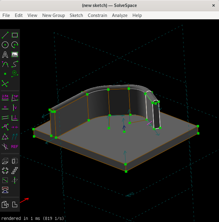
@Symbian9 The new Revolve tool does exactly what you want, but in the case of cylinders is seem to trigger some NURBS issues at times. It does allow you to create that object very nicely and drag it without assembling parts from different files. @supertaz If your path consists of straight lines and arcs, you can use the new tool to piece together a path. In the model shown here, the path was defined on the flat plate and can still be moved there and the extrusion(s) along the path will follow. Again, this sometimes triggers bugs but it's fairly good. Anything more than this and you're going to be waiting. But this is in the current master branch if you can build from source. This is NOT a general path-extrusion tool, it was done with a set of construction lines and some extrudes and revolves carefully constrained to get them to follow what's in the plane. I've attached the model too, but it will not work in any version but the latest. But let's not solve any specific problems in a feature request thread. There is a forum for that both on the website and on thingiverse. |
|
@phkahler I think I'm a few weeks behind right now, but I just pulled and I can rebuild. I agree with not solving specific problems, it was more of an example of what's hard to accomplish. Obviously there's no tools for doing this along a NURBS path, but the piecemeal approach with construction lines was what I was talking about above, just in an automated manner, instead of manually. I'm more concerned with managing to get it watertight, etc. doing it piecemeal, but there's no reason that shouldn't be possible. Some of the curves on the glass look like they might be NURBS, though (not on the other replacement she got, but this one matches the OEM glass, and I haven't measure it yet). Once I measure and attempt it (assuming I can avoid using any NURBS paths), I'll update with whether the piecemeal approach created a correct model. If it works properly, automating it would be a good feature, at least until someday there's a true arbitrary path extrusion feature. |
|
I have some questions about this feature and how the UI might work. Would the path be predefined? If so, how? Would it be good to have something equivalent to multiple repeated extrudes, but with the new copies of the sketch in arbitrary positions and orientation in space? If so, how should those locations be defined? How should we deal with the control points between copies? (no control points would just try to make a straight line from old point to new point. A single control point could try to make a circular arc. Two control points would allow a cubic spline between them. All control points would need to be handled in a similar way as a group. In each case, how would the UI work? Should resizing the sketch at each station be possible? Must it be possible to change entities? - shape blending. This is of course the most difficult case. I'm just trying to gauge the level of importance and practicality of these things. Is there some other way to view this feature? I'm not familiar with how it's done in other CAD programs so I'm thinking in terms of SS interface as well as what I know about its internals. Much of this is not easy, but I'm starting to see some possibilities. |
|
@phkahler In my imagination, the Loft feature looks like this. I start with a 2d sketch, like usual. I select New Group → Loft. Now I can draw a path in 3d, and each chunk of the path generates one of:
This path is not arbitrary. It has to:
Control points. I can think of three possible approaches here.
Now, this is quite ambitious. I think an implementation that only handles lines and arcs (not beziers) and has no control points would already be extremely valuable, and open up tons of new applications. What do you think? |
|
@whitequark Has the right idea. While the control point ideas are good (and would make great enhancements), they are solving for problems that are usually handled in separate tools (loft, rail, and cover for instance) or are handled by multiple curves (i.e. you have a separate version of the tool where you define two path curves if you want to scale along the path). All of the constraints are correct, and it can be an issue if the segments have different normals, so it needs to either fix the normals or mark normals that are incorrect (lots of mesh operations have these issues, even when all the lines/curves are connected, some tools try to figure out what a surface should look like and that math gets confusing when they're pointing in different directions and you wind up with twists and self-intersecting surfaces and odd geometry - or just an error). Those are my thoughts...this is moving in the right direction for sure. I ended up using my commercial package for the part (and upgrading it because I accidentally upgraded the machine it runs on to Mojave, which the old version didn't work with); there was no other way to handle it, unfortunately. This feature would still be a huge leap forward (even if beziers aren't handled in the first iteration). |
|
Thinking more about this and the idea of a circular arc connecting copies of the sketch like Revolve but with a different UI. So a base sketch and then a copy some distance away like an extrusion. But you can also move that copy around and the generated shell/solid will bend along a circular arc. Is that what you were thinking @whitequark ? It's hard to imagine "Revolve" for that because that requires an axis of revolution which becomes infinite radius when it's a straight extrusion and would flip sides depending which way you pulled the curve from there. Then I realized: For an extrusion like that (a circular arc) there are two copies of the sketch which can be seen as mirror images where one is reflected across a plane that bisects the revolve surface. It may be possible to define a different type of revolve/curved-extrusion like this, where the copy is defined as a reflection of the original and the free parameters (handled by the solver) are the definition of the reflection plane (not shown to the user). This could handle a straight extrusion with the plane half way along the extrusion and parallel to the sketch. You'd have some freedom to move or constrain the "new" end. This might even be initiated (UI) by revolving a sketch without selecting an axis first. From an interal PoV the control points for the curved surfaces (which you never see) are just the original control points projected onto the reflection plane with appropriate weights (easy to calculate). That all brings me to another thought. Should there be some kind of "mirror" group which works even with shells and allow similar positioning/constraint of the copy? This would involve the exact same internals for reflecting entities described above. Of course we might also allow the user to define a reflection plane somehow (axis if it's only a sketch). I mostly wanted to document this train of thought and see if it makes sense or would be useful. I'm not going to try this in time for 3.0 and if/when I do it will sit in an experimental branch for a while. |
It would be cool if SolveSpace would has "Mirror" feature. As for me, easiest way for solve this task would be adding "☑ mirror every even copy" option for "Step Rotating" group. For example, if set 2 copies (with original) in "Step Rotating" group we would get mirrored solid from one half solid (previous group). |
There's an issue for those, #72. I never got around to implementing them unfortunately... it comes up quite a bit. |
|
@whitequark While I had seen issue #72 before it was not in my concious thoughts when I realized mirroring across a plane can produce entities for a curved extrude! It's funny because I used the entity replication from Step-Rotating for the new Revolve group - no new solver work required. It seems there can be several uses for these things. Anyway, JWs comments on mirror planes suggest the same implementation in the solver as I outlined above. BTW I'm really not excited about how SolveSpace handles polymorphism of entities, but I'm getting used to it. |
I agree with you entirely. I want to improve it... but that is an enormous amount of work, and SolveSpace did not even have a testsuite before I added one, and the one I wrote is far from being complete. @rpavlik has been making good changes in that direction, too. So, it's something that I'd like to see eventually fixed. |
|
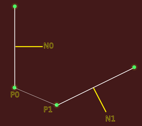
@jwesthues In the diagram below, we're looking at a side view of some sketch containing point P0 with the desire to drag a copy of it to P1. The sketch (unit) normal vectors are N0 and N1 respectively. If we consider vector D to be (P1-P0) but with unit length, then it turns out that the quaternion to rotate from station 0 to station 1 is Q = (w,x,y,z) where x,y,z is just the cross product of N0 x D and w = sqrt( 1 - x * x - y * y - z * z ). If we apply that rotation to point P0 and then subtract from P1 we get the translation needed to go along. This will be true for any point and its copy at the new station, so it's not really dependent on a particular point.
If we move from the base sketch (station 0) to station n, we can always get there directly by using a rotation (quaternion) and translation QnTn. The thing is QnTn needs to produce the same result as Q(n-1)T(n-1)QT, where the unsubscripted Q and T are constrained to behave as described above to get from one station to the next. We may need to symbolically transform the base sketch normal to station n-1 to write the constraints, but it's not clear what to do about the point used to tie the Q and T together. Maybe we could just transform the sketch origin and use that, since we're really defining constraints between a pair of transformations rather than constraints between specific entities? I'm thinking we'll use the direct transformations to get from the base sketch to the N stations to avoid accumulation of numerical errors from applying N transformations. I also need a place to store the Qn and Tn parameters for each station. If it were a single group per station they would naturally go in the group parameters, but we're going to be dynamically creating many of them. Would it make sense to create an invisible "station" entity to hold those parameters? That may be a bit redundant since every entity will be of copy type N_ROT_TRANS and will have references to those parameters? Thoughts on the math are welcome. Oh, one question there. What is the associative rule to swap the order of quaternion transforms and translation - rewrite Q T as T Q ? |
|
I'd probably implement this feature without any interaction with the solver? Like the user would select a plane sketch and the sweep trajectory (a chain of curves all tangent to each other at their endpoints, with one endpoint lying in the sketch plane and normal to that sketch plane), and you'd compute everything from that. That would avoid the need to compute anything symbolically, greatly simplifying life. I think here (unlike for the Booleans) you can actually get some help from the academic literature, for example Chapter 10 of "The NURBS Book". As you say, the goal is to translate the plane sketch along the trajectory, while rotating it to keep the sketch normal to the trajectory. The remaining free variable is the twist about that normal, for which you need some kind of heuristic (e.g., to minimize the change in that twist). That all looks pretty messy and approximate; you might prefer to start with lofting (select two or more closed curves, and fill a surface in between them), which looks easier mathematically though still nontrivial. Re rotations and translations, are you just looking for R*(p + x) = R*p + R*x where R is the rotation and x is the translation, or something further? I find it generally easiest to think in terms of 3x3 matrix math, and treat the quaternion as just an implementation detail for the rotation matrix multiplies. |
No, I want to know how to reorder them. So Q then T is replaced by T' then Q'. I want to be able to reorder a sequence of rotations and translations so I can then combine them and end up with just one rotation and one translation. |
I think you can just expand out the matrix math? Like if you want to apply rotation R1, then translation x1, then rotation R2, then translation x2, then you have R2*(R1*p + x1) + x2 = R2*R1*p + (R2*x1 + x2) which is equivalent to rotation by R2*R1 then translation by R2*x1 + x2. The rotations are of course implemented as quaternion operations rather than actual 3x3 matrix multiplies. |
|
Yeah that's by far the easiest, turn it all into isometries in Eigen (or equivalent) - matrices - then back to position and quaternion at the end if you like. |
|
@rpavlik I'm devising a set of constraints to apply to the parameters of rotate-translate transformations. Example: when you extrude, the new points are translations of the existing points but the parameters of the translation are constrained to be orthogonal to the sketch plane. I want to use the more general rotate-translate transform for stations along a complex path, but I want to constraint them from 6DoF to 3DoF so each segment follows an arc or a straight line. Hence I need to algebraically constrain the parameters of 2 6DoF transforms. It's starting to come together in my head and on paper ;-) |
|
Just documenting my most recent thoughts on this, but would also like input from @jwesthues @ruevs and anyone else who may understand either the math or the internal structures. What I'm thinking now is segmented extrusions with multiple segments in one group where:
We shall have the following segment types: Each station will need 8 parameters to define how to transform the base sketch to that location. Similar to the copy-type that is currently used for linking, but with scale added as an 8th parameter (vs in the text window for the group). All entities at a given station will use the same 8 parameters for their transform. Constraints: For an example, lets consider a curved segment from S2 to S3. We want the rotation to be about an axis in the S2 and S3 planes so the extrusion does not need to twist. If we compute the quaternion Q going from Q2 to Q3, we can apply a constraint that the vector part of Q dotted (dot product) with N2 is zero. Intuitively this means the rotation axis to get from S2 to S3 has no axial component (twist). Likewise, doing twisted frustum would require the vector part of Q to be perpendicular to the plane. of S2 (which may require a U and V vector in addition to the normal). I think we need to implement symbolic quaternion "division" here to find Q such that Q2.times(Q) = Q3. This might just be something like Q = Q2*Q3.conjugate()? I need to check the quaternion book. For a curved segment the translation from S2 to S3 must lie along the "half way" vector N2+N3. I think this is true for all the listed segment types. Obviously for a straight segment we'd have Q2=Q3. It seems like we should have some per-segment parameters. For example, if we create multiple frustum segments with different slopes, should we have an option to have a smooth join at the station joining the segments? Where would this flag live? Where do we define the segment type? If someone changes the segment type, how do we delete the constraint equations and create new ones? Or do we just regenerate and build the equations then? I've finally got the math fairly complete in my head, but these software questions remain ;-) Building the shells should be easy (to me anyway) once the station handling is all implemented as outlined here. The result of this will not be extrude-along-a-path in the traditional sense where the path is predefined. It will allow creating the segmented extrusion prior to pinning it down, which I think is a very solvespace way of doing it and more fun to use than other tools. |
|
This probably isnt helpful but it seems as though FreeCAD supports this kind of sweep operation, so for usecases where being able to do that is necessary, that may be a better tool for the job. That said, I love the UI of solvespace though! it feels a lot more intuitive to me |
|
Yeah I would much rather use SolveSpace for everything if I can, and missing lofts is one of the things that makes this impossible for me. |
Extrude is currently limited to linear extrusions, as far as I can tell, and lathe, even with the helical mode in development, can only extrude around an arbitrary normal (helical mode just allows for interruption and translation, as I understand it). When dealing with a part whose profile has an arbitrary number of curves and a lip, the only way I can find to create the part is to do a linear extrude of the arbitrary shape and subtract an inner extrusion. This is a fairly standard mode of design, but it poses a problem when that lip needs a radius. As there is no way to extrude a profile along an arbitrary path, one can't simply design the profile of the lip and then extrude it along the orignal profile curve for the base linear extrusion (which is a common route to take in some CAD software), and since there aren't any 3D tools, it's not possible to simply apply a tool to the faces to create the edge profile needed (this is another route commonly taken by CAD software).
Right now, the primary things standing in the way of SolveSpace being my primary go-to package (and possibly even avoid paying for future upgrades to my commercial packages fingers crossed) are the lack of edge tools and the inability to do any kind of skin, patch, loft, or hull operations (while not interchangeable, one or two of them can usually be used to solve for the absence of the others).
The text was updated successfully, but these errors were encountered: